English
 中文简体
中文简体 عربى
عربى


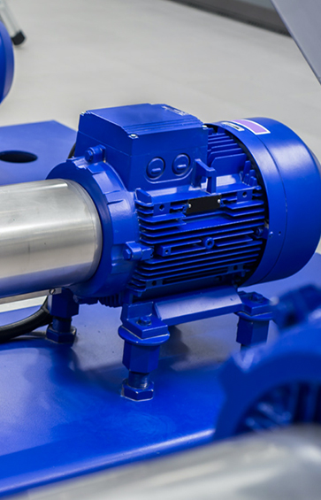
Technicians and hobbyists restoring machine tools often face a common challenge: a lathe or saw that takes "about an hour to stop" after power is cut . This long coast-down time not only reduces productivity but also poses a safety concern. A frequent question on technical forums is whether DC injection braking—a method well-established for three-phase motors—can be effectively applied to a Single Phase Brake Motor . Users want to retrofit this capability without replacing their existing motor with a factory-built Three Phase Brake Motor and VFD system.
The short answer is yes, DC injection braking can be highly effective for single-phase motors, but the implementation differs significantly from the three-phase approach. While a three-phase system can inject DC into the windings relatively simply, a single-phase motor—particularly a Permanent Split Capacitor (PSC) or Capacitor-Start design—requires careful circuit design to handle the start and run capacitors.
Understanding the Mechanism
DC injection braking works by applying a direct current to the motor windings after the AC power is removed. This creates a stationary magnetic field in the stator. As the rotor continues to spin, it cuts through this field, inducing currents in the rotor bars. These induced currents interact with the stationary field to produce a braking torque that rapidly slows the motor .
Three Phase Simplicity: In a Three Phase Brake Motor, two of the three leads are typically shorted together and connected to one side of a DC source, with the remaining cause connected to the other side. The DC flows through a combination of windings, creating multiple stationary poles.
Single Phase Complexity: A Single Phase Brake Motor presents additional challenges. The motor contains both start and run windings, often with a capacitor permanently connected (in PSC types). Any DC injection circuit must account for these components, as applying DC through a capacitor can damage it or render the braking ineffective . The typical approach is to disconnect the capacitor and apply DC across the main (run) winding only.
DIY Approaches and Circuit Considerations
The hobbyist community has developed several workable circuits for adding DC injection braking to single-phase motors. One classic design from the 1950s, detailed in US Patent #2.922.097. uses a relay system to charge a capacitor from the AC line, then discharge it through the motor winding when the stop button is pressed . A more advanced "self-excited" approach combines regenerative braking (using the motor as a generator to charge capacitors) with final DC injection, providing smooth braking across the entire speed range .
Critical design factors for a DIY system on a Single Phase Brake Motor include:
Voltage and Current Levels: For a small motor (e.g., 1/20 HP), a DC voltage of around 12 volts applied to the main winding may be sufficient. For larger motors (1 HP and up), higher voltages are required, and the circuit must handle significant surge currents . The DC current should ideally be similar to the motor's full-load AC current rating .
Component Ratings: Relays and switches must be rated for inductive DC loads, which are much harder on contacts than AC loads. Forum discussions highlight that standard AC relays can fail quickly due to contact welding from the high inrush current of a capacitor discharging into the motor winding .
Timing and Delay: A brief delay (e.g., 250 milliseconds) after removing AC power is necessary to allow the motor's magnetic field to collapse before applying DC. Applying DC too soon can cause the motor to act as a self-excited generator, potentially creating dangerous voltage spikes .
Duty Cycle and Heating: Each braking cycle dissipates the motor's kinetic energy as heat in the rotor and windings. This counts as a "start" for thermal purposes. For applications cycling four times per minute, thermal buildup could be significant, potentially exceeding the motor's starts-per-hour rating and requiring forced cooling .
Limitations and Practical Considerations
While DC injection braking can be effective, it has inherent limitations that users should understand before committing to a DIY retrofit on a Single Phase Brake Motor.
Speed-Dependent Torque: With simple voltage-controlled DC injection, braking torque is lower at high speed and increases as the motor slows down. This can cause a "jerk" at the very end of the stop. Current-controlled systems provide flatter torque but are more complex to build .
Effectiveness at Very Low Speeds: At near-zero speed, the braking torque from induced rotor currents disappears entirely. The rotor finally stops due to residual magnetic "cogging" between stator and rotor teeth, not from the DC injection itself . This means the final stopping position may have some variability.
Capacitor Handling: For PSC motors, the run capacitor remains connected across part of the winding. A DIY circuit must either isolate this capacitor or be designed to work around it, as applying DC through it is not recommended .
Component Availability: Building a robust system requires high-voltage capacitors (typically 400VAC or higher metallized polypropylene film types, not electrolytic), high-current rectifiers, and industrial-grade relays. These components can be expensive to purchase new, though surplus or salvaged parts may be an option .
Factory-Integrated Solutions vs. Retrofits
Given the complexities, many users find that upgrading to an integrated solution is more reliable than retrofitting. For a Single Phase Brake Motor, options include:
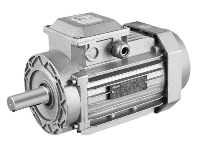
Factory-Built Brake Motor: Zhejiang Ligong Motor Co., Ltd. offers single-phase motors with factory-integrated DC brakes. These units have the rectifier and brake coil properly sized and thermally protected, eliminating the need for external DIY circuits.
External Electronic Brake Modules: Commercially available DC injection brake modules are available for single-phase motors up to certain horsepower ratings. These units handle the capacitor isolation, timing, and current limiting internally, providing a plug-and-play solution .
Upgrade to Three Phase with VFD: For applications requiring frequent stops or precise positioning, replacing the single-phase motor with a Three Phase Brake Motor and a Variable Frequency Drive (VFD) offers nice control. VFDs provide programmable deceleration ramps, DC injection braking as a built-in function, and the ability to tune stopping characteristics .
For critical applications or high-duty cycles, the reliability and simplicity of an integrated brake motor or a VFD-driven three-phase system often outweigh the cost savings of a DIY approach. Zhejiang Ligong Motor Co., Ltd. recommends evaluating your specific operational requirements—stopping time, cycle rate, and desired repeatability—before deciding which path better serves your application.